Reverse engineering the Finalmouse Centerpiece Pro
The Centerpiece Pro is a keyboard with a built-in under-key display and translucent keys. After years of waiting, and with more and more technical information being released about it, I knew immediately that I would have to reverse engineer it the moment it landed on my desk.
What makes the Centerpiece special?
As already mentioned, the main attraction of the Centerpiece Pro is the keyboard itself. You can build interactive “skins” for it, and these skins can react to keypresses, play animations, spawn particles, or really do anything you can think of. All of this works because the Centerpiece Pro runs an Unreal Engine host app on top of an Android system.
The detail worth holding onto is that there are two separate systems inside the board. The MCU handles the actual keyboard logic, scanning the key matrix and reporting keypresses, while the Android system handles everything to do with the display. They are independent of each other, talking over an internal link rather than running as one unit. That separation is smart, because a microcontroller can scan a key matrix with low latency, while a full SOM is what drives the display and the skin engine.
SDK
Before I got adb access or made any hardware mods to the Centerpiece, I wanted to put my own interactive skins on the keyboard. The absence of an official SDK made that non trivial.
What I did have were the .pak files from the stock skins. A .pak file is just Unreal Engine’s packaging format, a container of cooked assets like Blueprints, materials and textures that the engine mounts at runtime. They are trivial to unpack with a tool like FModel. Thankfully none of this was new territory for me, I already had extensive experience reverse engineering Unreal Engine games from my time digging into Aim Gods (fans of the game can expect something very soon), so I had a good idea of what to look for.
Every skin referenced the same native module, and at its center a class called USkinCreatorLibrary: a Blueprint-exposed library with public functions for interacting with the device, and delegates that skins bind to in order to receive keypresses. This was clearly the de facto SDK.
I only had references to that class, not the class itself. USkinCreatorLibrary is native code compiled into the host app, and compiled code never ships inside a .pak. Instead, cooked Blueprints reference native classes, functions and delegates by name, and those references get resolved at runtime through Unreal’s reflection system. That has a nice consequence: if the .pak has to resolve these references at runtime, then all the information needed to do so must be in the .pak itself. The full function and delegate signatures, names, parameter types and return types, are sitting in the serialized data, and FModel shows all of it.
So I didn’t need Finalmouse’s source, just declarations that look identical to the reflection system. I stubbed out the whole library in my own Unreal project, redeclaring every function and delegate with matching signatures and empty bodies. The editor was happy with that, so I could build skins against USkinCreatorLibrary like a normal API and cook them into a .pak of my own. The empty bodies are irrelevant, since they get left behind at cook time anyway. All that survives in the package are the by-name references, and on the device, reflection resolves them against the real USkinCreatorLibrary in the host app.
The one thing to be careful about is that the matching has to be exact. A wrong parameter type or a misspelled delegate and the runtime lookup fails.
ADB
Triggering ADB via the HID command did get us the authorization dialogue on the keyboard’s display, so the channel was clearly there. The problem was that there was no way to actually accept it: the Centerpiece has no touch input and no way to feed input into the Android side, so the prompt just sat there with no way to answer it. Without being able to authorize the connection, ADB was a dead end from software alone, which is what pushed me toward opening the board up and going after the hardware instead.
Opening it up
To open the Centerpiece up, you have to remove the 8 screws on the backplate. One thing to watch out for: the top 4 and bottom 4 screws are not the same and use different threading, so be careful to put the right ones back in the right holes during reassembly, or you risk stripping the threads.
The first thing you see after opening the board is a PCB on the left. There is one larger PCB and one smaller PCB connected to it through a SO-DIMM style connector. A SO-DIMM connector is the same edge-connector form factor used by laptop RAM, and here it is being reused as a board-to-board connector. The smaller board is the SOM (System on Module), and it carries the Android system. The idea behind a SOM is that the expensive and complicated part, meaning the application processor, RAM, and storage, all live on one self-contained module, and the product-specific board just provides power, connectors, and whatever peripherals the device needs. In this case the labels on the SOM point at a Firefly Core-3566JD4 module, which puts a Rockchip RK3566 at the heart of the Android side. The larger board is the main PCB, which handles the actual keyboard functions and also provides the connector and pins for the SOM.
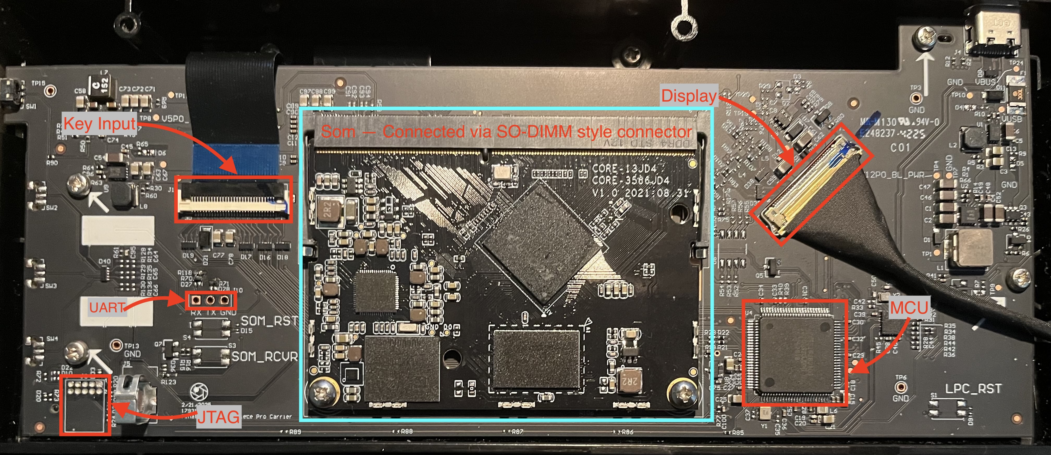
There are two very promising pinouts visible here: a UART header and a standard 10-pin Arm Cortex debug header for SWD or JTAG. UART is a simple two-wire serial interface (plus ground) that is almost universally used as a debug console on embedded Linux and Android devices, which is exactly why it is the first thing you go looking for. SWD and JTAG, on the other hand, are lower-level interfaces that let you halt the CPU, read and write registers, and step through code, which is far more powerful but also far more involved to use.
My initial guess was that the UART pinout connects to the SOM and the JTAG connector goes to the MCU. My reasoning was that there is really no need for low-level debugging on the SOM, since it is an Android system running high-level software like the SkinEngine, and a serial console is the natural way to interact with that. On top of that, Finalmouse already uses these JTAG pinouts on their mice, so it fit the pattern.
Getting access to the MCU is not all that interesting anyway, since you can already dump the MCU flash by putting it into recovery mode. You do that by holding the button on the side and plugging the keyboard in at the same time. Most microcontrollers ship with a built-in bootloader that exposes exactly this kind of recovery path, so the firmware is already within reach without touching JTAG at all.
That leaves the UART connector as the interesting target. I did not have a UART adapter on hand at first, so I repurposed an Arduino UNO to pass serial IO straight through. That gave me no output at all. At the time I assumed this was because the Arduino and the SOM were running at different baud rates, but in hindsight that explanation does not hold up. UART has no shared clock line, so both ends have to agree on the bit rate ahead of time. If they disagree, the receiver still sees the line toggling and still samples it, it just samples at the wrong moments and decodes garbage. In other words, a baud rate mismatch would still have produced output, just garbled and unreadable output, rather than total silence. Silence means no signal reached the line at all, which is a different problem entirely. By the time I worked that out I had already ordered a proper UART adapter, so I just had to wait a few days to test it correctly. For reference, the correct baud rate is 1.5 million, as documented on the Firefly wiki.
When the UART adapter finally arrived I was very eager to try again, since none of my other efforts had borne any fruit. I opened the keyboard back up, connected jumper wires to the connector, plugged them into the adapter, and got… nothing. So the UART pinout was not live.
My first thought was that some special debug flag had to be triggered to bring it up. I tested the UART connection in SOM recovery mode and still got nothing. At that point I was frustrated enough that I stopped for a day or two to clear my head and come up with new approaches.
Somewhere in those two days it occurred to me that I had never actually verified the UART adapter was even connected to the SOM in the first place. For the UART signal to reach the SOM, there has to be electrical continuity between the UART pinout and the SO-DIMM SOM connector. So I grabbed my multimeter, set it to continuity mode, and checked every single SO-DIMM pin against the UART connector to see if there was any connection at all, and there was nothing. That ruled out my software theories in one go: the issue was not a missing flag or the wrong mode, the pins weren’t live.
The next step was to trace the actual routing on the PCB, which is how I noticed that some resistors were missing. (On the PCB, resistors are prefixed with R, so resistor 10 is labelled R10.) Empty resistor footprints are extremely common on production boards. Manufacturers route a signal through a footprint and then choose whether to populate it, which lets one board layout serve several configurations. Leaving a resistor unpopulated is an easy and cheap way to break a connection that the hardware otherwise supports and might only be used for debugging.
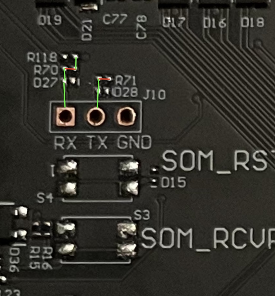
This looked promising. The RX and TX pinouts do route somewhere, but to get there they have to pass through a few resistors. To check whether UART was actually live, I held a couple of jumper wires against the right side of R71, turned the keyboard on, and there it was: serial output from U-Boot. U-Boot is the bootloader that runs before the kernel on most embedded Linux and Android devices, and seeing its log on the wire confirmed both that the line was alive and that I finally had the right baud rate.
Holding the jumpers in place by hand is tedious, though, and I definitely did not want a flaky connection while writing to flash, so I needed to figure out which resistors were actually critical. A multimeter makes that easy to work out by checking which footprints sit in series on the RX and TX paths. This is also where it became clear that Finalmouse had deliberately stripped some of these resistors to stop people from getting serial access. My first hypothesis was that R118 and R71 needed to be bridged, but bridging those put the keyboard into a boot loop. After more testing, I landed on R70 and R71 as the missing pair. Bridging them with a tiny blob of solder made the UART pinout work fully. In the picture I marked continuity with green lines and breaks in continuity with red.
Getting ADB
This was probably the most tedious part of the whole project, and it took a lot of trial and error.
To start with, it is possible to enable ADB through a HID command sent to the keyboard. ADB, the Android Debug Bridge, is the standard channel for talking to an Android device from a host PC, and it gives you a shell, file transfer, and more. The catch is that ADB is an authorized protocol. On the first connection attempt, an Android system pops up a dialogue asking you to authorize the connection, at which point an RSA public key from the host PC is pushed to the device. The device stores the keys it trusts, usually in /data/misc/adb/adb_keys or in a vendor-provided list, and on later connections it checks the host’s key against that list. If the host’s key is already present, the host is treated as already authorized and no prompt appears. One developer key is pre-authorized on the device, so to get in we either need to get our own ADB key authorized, or put the device into an unsecured ADB state where the check is skipped entirely.
The behaviour is controlled by an Android system property called ro.adb.secure. When it is set to 1, ADB requires authorization. The ro. prefix marks it as a read-only property, meaning it is meant to be fixed at build time rather than changed at runtime, which is part of why simply trying to override it turned into such a saga.
The first thing I tried was overriding the boot parameters in the U-Boot console. None of the flags I set had any effect. I assume this is because the values we write get overwritten later in boot, and only the last values written actually take effect. The kernel command line and the init sequence get the final say, so anything I set early was simply clobbered. Dead end.
The next thing to investigate was the contents of the boot partitions. I found multiple occurrences of ro.adb.secure=1. That sounds like a trivial fix: flip them and ADB should become unauthenticated. But no, adb devices still reported the device as unauthorized. So I needed to understand how these parameters are actually loaded. It turns out Android first tries to read them from the system partition, and only falls back to the boot partition if they are missing from the system partition. So, just patch the system partition, easy, right?
Not quite. I found ro.adb.secure=1 in the system partition and patched it, which worked fine, but ADB was still authenticated. So where were the parameters actually coming from? As it turns out, Android 11 uses a virtual A/B snapshot system, and I had written to the system_b-cow partition, which is only read when an OTA update is being merged.
A bit of background makes this make sense. A/B (also called seamless updates) keeps two complete copies of the system, slot A and slot B. The device boots from one slot while an update is written to the other, so a failed update can never brick the device, it just falls back to the slot that still works. Virtual A/B takes this further: instead of keeping two full physical copies, the second slot is stored as a copy-on-write (COW) snapshot layered on top of the active partition, which is what the -cow suffix marks. That snapshot only becomes relevant while an update is being merged. So I had spent my effort patching a partition that the system does not even read during a normal boot. Not the partition that matters at boot.
At this point I decided to stop guessing and read the LP metadata properly. Modern Android ships everything inside one big super partition and then carves logical partitions out of it dynamically, rather than giving each one a fixed slice of the flash. The map describing that layout is the LP metadata (managed by liblp), and it is what tells the system which on-disk regions belong to which logical partition. The super partition keeps three copies of this metadata at known offsets for redundancy. System A and System B share the same physical disk space, and system_b-cow is irrelevant for normal boot. Armed with that, it was finally time to patch the correct byte on the region that system A/B actually maps to. I patched it, rebooted the keyboard, and there we go. Now we had ADB access to the system.
Post ADB
Now that we have ADB, what can we actually do with it? Running adb shell drops us into a shell on the system, but it is a wildly unprivileged one. On a production Android build the shell user is heavily boxed in, both by traditional Unix permissions and by SELinux, so getting a shell is only the first step. The next step was to look for any way to escalate privileges.
The obvious move is to list which ports are open on the device, in case there is a service listening that might be exploitable. A locally listening service is a great target because it is already running with whatever privileges it was started with, and if it does not authenticate its clients, anyone who can reach the port inherits those privileges. That scan immediately turned up a service called rootshelld listening on port 5557. This seemed too good to be true. Surely it must be authenticated? The quickest way to find out is to just connect to it with netcat, and there was no auth prompt, no challenge, nothing. Just a shell.
That shell runs as system with the SELinux context u:r:rootshelld:s0. I am not confident enough about SELinux internals to make strong claims here, but the short version is that on modern Android, SELinux confines every process to a domain and the policy spells out exactly what each domain is allowed to touch, which is why “root” alone does not mean unrestricted access anymore. In practice this rootshelld domain gave us a shell that was even more capable than an ordinary root shell would be on this device. My guess is that rootshelld was meant to be removed before shipping, or at least gated behind some kind of authentication. Either way, it works very much in our favour.